1. General
1.1. Linear Gas Burner
The Alsaflam Gas Burner is a high-performance forced air burner that is easily adapted to the various needs of the industry. Its linear geometric heat power distribution promotes the efficient transfer of thermal energy to the process requiring heat. Direct heat processes benefit from this feature.
Its unique design, coupled with the right fuel supply and combustion settings, enables it to deliver exceptional results. Safety is ensured first by compliance with industry standards and specifications, and secondly, and most importantly, through the use of state-of-the-art equipment and techniques such as gas-air ratio regulation.
1.2. Safety Precautions
When properly installed, adjusted, and operated, gas burners do not pose any operational or safety problems.
The Alsaflam Linear Gas Burner is installed by qualified personnel in compliance with all Standards, Specifications, and Generally Accepted Industry Practices in all areas concerning fuel and electrical supply. Particular attention is paid to automated electrical controls.
In order to ensure optimum performance, the adjustment and operation of the Alsaflam Linear Gas Burner is carried out by a professional who is specially trained in gas burner techniques.
1.3. Compliance with Standards
The Standards and Specifications applicable to the equipment and to its place of installation must be followed.
The Alsaflam Linear Gas Burner conforms to the Standards and Specifications that apply to it. In particular, as far as the supply from Alsaflam is strictly concerned, it conforms to the provisions of the following
EEC directives:
⇒ 89/336/CEE, electromagnetic compatibility
⇒ 73/23/CEE
⇒ 89/392/CEE from June 14, 1989 concerning “machines”
and complies, strictly as far as the supply from Alsaflam is concerned, with European Standard EN 746, Parts 1 and 2, relating to the safety of Industrial Thermal Equipment.
2. Description of the LGB
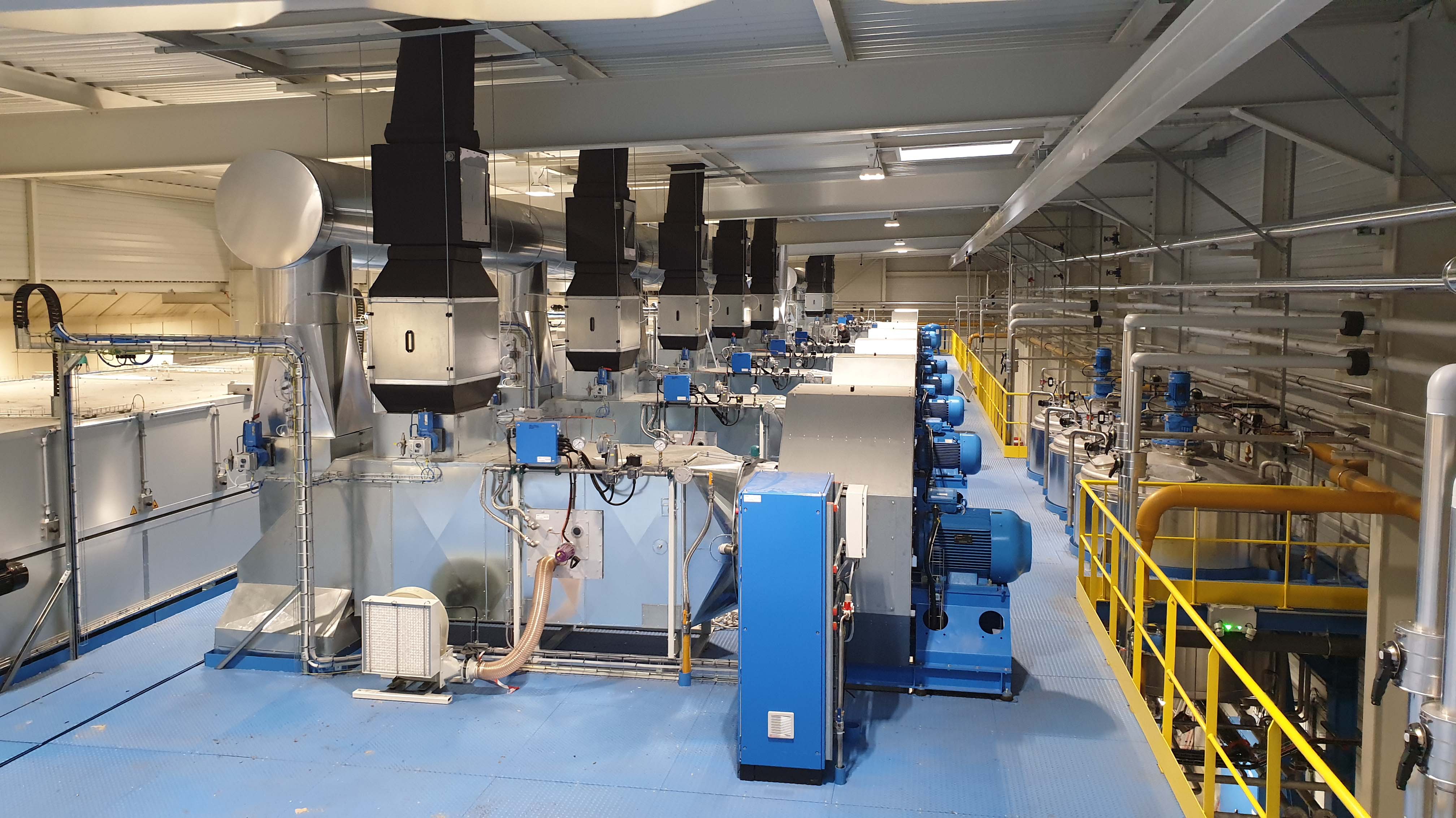
The following description is an example. The Alsaflam Company designs and builds its burners according to their location and use. The actual installation can therefore differ from the sample below.
2.1. Composition
The Alsaflam Linear Gas Burner consists of two concentric enclosures fed with air and gas respectively. The outer tube has frustoconical-shaped openings responsible for materializing and stabilizing the flames.
Air and gas mix at the tip of each injector to create a flame in each conical opening. The side by side orientation of the openings generates a line of flame with a linear shape, which is the basis of the name of the Alsaflam Linear Gas Burner. In each opening, an injector is supplied with gas through the inner tube.
In each opening, an injector is supplied with gas through the inner tube.
The air is set in rotation by a turbulence ring machined in the shape of a propeller.
The gas injectors are made by precision bar-turning, which gives them a precise flow and helps create a line of flame with a uniform power distribution and that is homogeneous at all speeds. We use “fre jet” gas injectors for our Alsaflam burners.
2.2. Air Supply
The Alsaflam Linear Gas Burner is fed under high and stable pressure by a constant-speed air turbine.
An air filter, located upstream of the air turbine, protects the entire combustion plant from suspended dust and fibers. The cleanliness and the good condition of this filter are of the utmost importance. When there are several burners on the same machine, the filter and the fan may be shared.
An air pressure switch monitors, through automated controls, the presence of sufficient pressure for the proper operation of the burner.
The position of the air flow control butterfly valve determines the rate of air flow through the burner and consequently the power supplied by the flame during operation. The air valve servomotor is controlled by the temperature regulator, through the automation controls that also manage its position during the power-on and power-off phases.
When the operating conditions of the machine permit, variation of the combustion air flow rate is obtained by modifying the rotation speed of the fan instead of the air butterfly valve.
2.3. Gas Supply
The Alsaflam Linear Gas Burner is fed under a pressure of 100 to 300 mbar by a gas pipe whose diameter is determined by the gas flow rate needed.. The burner is supplied with gas by a shut-off valve followed by a flexible gas line and a gas filter. The optional manometer allows the user to monitor the presence and pressure of the gas on arrival.
A gas pressure switch monitors, through the automated controls, the presence of sufficient gas pressure (gas presence pressure switch).
A gas manifold, consisting of a gas safety solenoid valve and a gas-air ratio regulator, delivers to the injectors the quantity of gas corresponding to the air flow rate supplied to the openings. The setting of the gas-air ratio regulator optimizes combustion at all operating speeds. The ratio controller also performs the class A solenoid valve function. A gas pressure switch ensures that, at any time and for every burner, the gas pressure does not become excessive (gas excess pressure switch).
Depending on the case, some of the components described above can be grouped together as multi-function components.
2.4. Flame Monitoring
After ignition of the gas-air mixture by an electric spark, the permanent presence of the flame is monitored by a flame detection device.
The flame-presence control process is carried out from a UV cell that detects the ultraviolet emissions emitted by the flame.
2.5. Controls and Automation
The Alsaflam Linear Gas Burner is inseparable from its electronic control and its automated processes. These are mainly provided by a regulation-compliant control and safety system cabinet, which is responsible for start cycle and run-time monitoring, a power pack, and a temperature control,


